Here is a DIY wideband loop rotator concept that should work with either stepper or DC geared motors and cost less than $30 to build. Let’s take a look.
After doing a bunch of research, I have arrived at a conceptual design for a DIY rotator. All of the electro-mechanical parts are readily available and cheap. All of the 3D printed parts can be handled by my 3D printer. So, here goes.
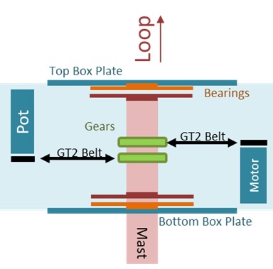
My fixed mount will be a 4′ mast of 1½ inch ABS pipe from Home Depot. My rotator will be built in a 6″ square plastic box, attached to the mast using a pair of 4″ Lazy Susan swivel bearings. As you can see above, the outside bearing is attached to the top and bottom box plates, using screws. The inside bearing will be clamped to the mast using 3D printed collars. I picked up these bearings locally at Lee Valley.
I got this wideband loop rotator concept from studying the SatNOGS rotator designs. My aha moment came when I realized it does not matter whether the mast turns or the rotator box turns, as long as one in fixed. In my case, the mast will be fixed, and the loop will be attached to the rotating box. Using an ABS pipe for the mast enables me to pass amplifier control CAT7 through the rotator.
My main use for a 3D printer will be to fabricate three things. First, the rotator box itself, as well as loop mount. Second, main gears. I plan to use GT2 timing belts, so the gears must accommodate these connections and be clamped to the mast. Third, mounting components including collars to hold the gears and bearings, as well as the motor.
Wideband Loop Rotator Concept – Some More Ideas
One of my biggest challenges is how to physically assemble the parts inside a cube. Obviously the box will need to be fabricated in several pieces. Haven’t figured this part out yet, but I will!
You can see that this concept can be made to work with either a Stepper Motor or a DC Geared Motor. Either could be attached with a continuous loop timing belt of the proper length. Different Arduino code would be needed, but the software and hardware drivers are readily available.
Another idea was to provide an absolute position sensor which is always on. You can do this with a multi-turn potentiometer connected through a suitable gear ratio and a timing belt. Since a wideband loop only needs to rotate 180º, 5 turns on a multi-turn pot should provide an Arduino with a pretty exact position reading.