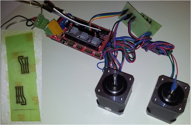
MPCNC motor management is pretty simple as long as you get the windings attached carefully.
The Mostly Printed CNC machine uses two stepper motors on each of its X and Y axis, and a fifth stepper to drive the tool up and down on the Z (vertical) axis. Each pair of horizontal steppers can be controlled by one motor driver on the RAMPS 1.4 control board. The picture above shows a RAMPS board with three stepper drivers (X, Y and Z) each with a small heat sink on top.
Since each of the horizontal stepper motors sits at the opposite end of a rail and move together, the only challenge is making sure that each moves exactly the same but in the opposite direction. The need to have opposite direction in movement is simply because they are facing in opposite directions physically.
This aspect of MPCNC motor management is achieved by simply reversing the polarity of one of the two coils in one of the opposing stepper motors. This means that you can use a single cable from your RAMPS controller board to the machine for each of the X and Y axis. And then do a reversal of one of the motor wiring pairs at the machine itself. Detailed instructions for wiring the steppers is provided on the Mostly Printed CNC web site.
MPCNC Motor Management – Keeping Everything Modular
One of my objectives in building this machine is to keep everything as modular as possible. This will make it easier to disassemble or move the machine. Perhaps more important, it will allow me to easily replace different parts and experiment with new approaches. For example, by doing all of the electrical wiring with modular connectors and terminal blocks under the work table.
So I thought I would etch a couple of small printed circuit boards to do the phase reversal in the stepper MPCNC motor management. As you can see in the above picture, this little PCB has one four pin connector for the control cable, and two four pin connectors for each stepper motor. The phase reversal is done on the PCB. This way, the color coding for the wires can remain the same.
I etched two PCB at the same time and cut them down later. My approach for using the toner transfer method and etching with hydrogen peroxide and muriatic acid (2:1) continues to work well.
These boards are still oversized because I am still not sure how I will mount them on the machine when I get to that point. I may drill a hole in each PCB and bolt it to something!
